
This post will cover my attempt at trying to make an electricity filter based on the diagram of the allmighty LAMPIZATOR from Poland. I chose his design because it was one of the first resutls I found in google and after reading all of his blogs and projects many times over, and seeing many images of him using an oscilloscope (and that makes you a genius on the internet) I decided he knows what he's doing.
First things first, his diagram:
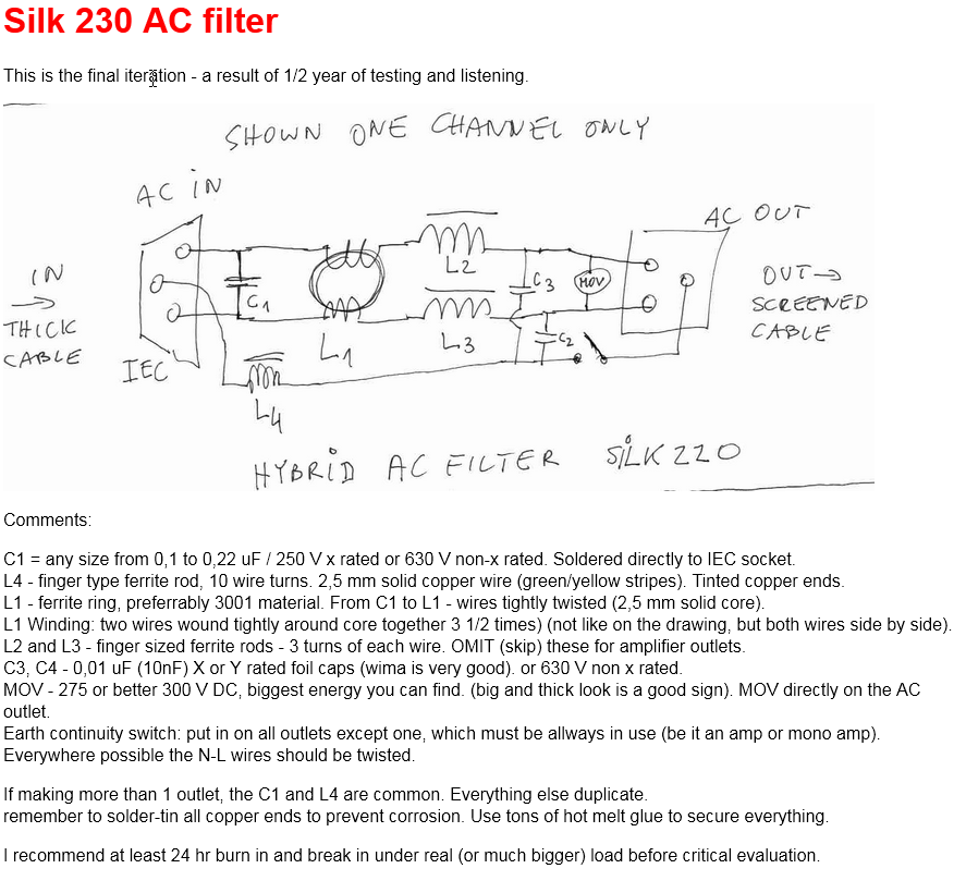
The explanation of how the circuit works can be found
here.
Planning
CAD version for visually impared like me:
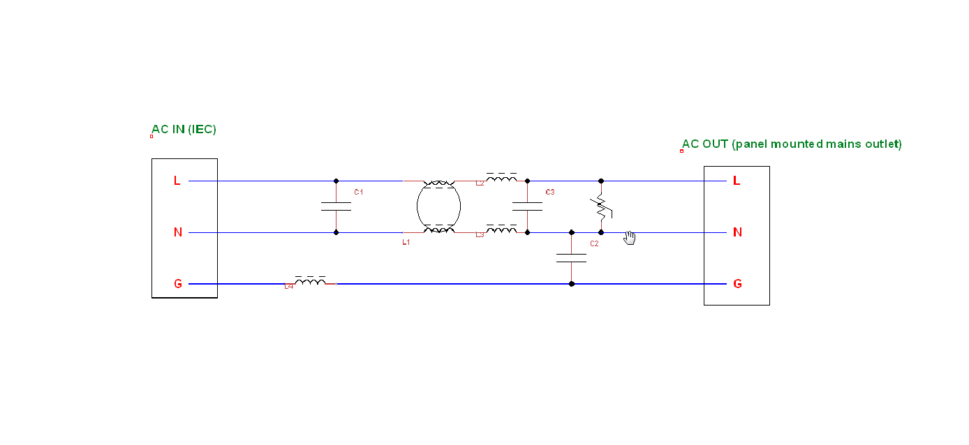
The software I used to create it is called TinyCad and its freeware.
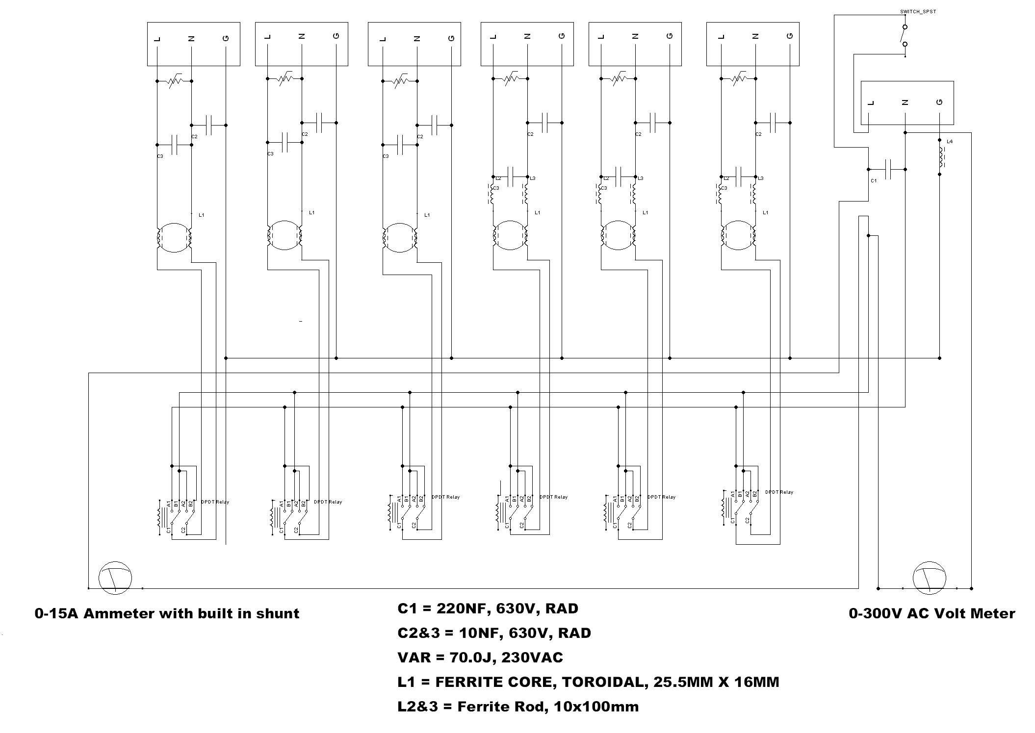
So since I wanted this my new filter to be stackable with other separates and have more then 1 output I decided to modify the circuit in a way that is as close to the original as possible.
On top of that Lampizator's Silk that he (rightfully) sells for a lot of money has flip switches to switch phases on the power cable that goes into your device which means that + and - get changed to - and + at a flip of the switch and because most HiFi electronics uses an unmarked figure 8 cable you can never tell if you plugged it in the right way round. You simply try all the combinations and pick the one that "sounds" the best to you, so I decided to add it. Additionally for extra bling I added an Ammeter and Voltmeter so it looks cool, expensive and Analog:
As for the component selection, I stuck with what mr. Lampizator used: "Finger Type" ferrite rod is roughly 10x100mm and the ferrite core size I picked is as close to what i saw on his product pictures as possible which is a 25.5x16mm torodial core.
To make it easier how the circuit is modified I circled the original parts in red:
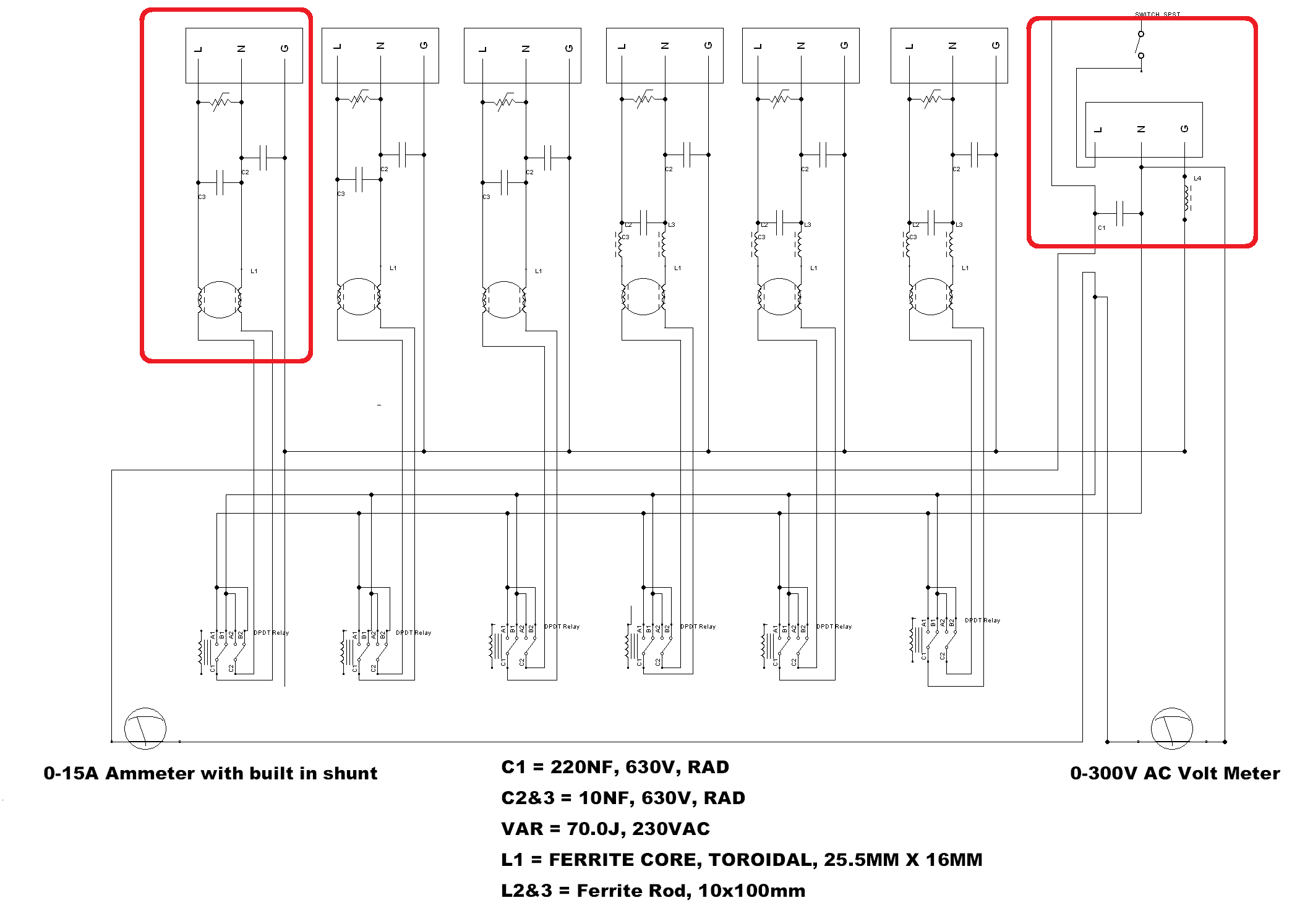
Obviously those 2 circled parts create the original circuit, the rest of it is more output sockets, the ammeter and volt meter and the phase flipping switched (DPDT).
I added those switches firstly because they look good and secondly because Lampizator himself used them as mentioned above. To add them it cost me about £40 extra but the end result will be worth it. If you don't know how a DPDT switch works it basically works like and ON/OFF switch but it has two ON positions except the second ON position has the negative and positive poles opposite to each other. So if ON position #1 is Negative Live, ON position #2 will be Live Negative thats how the whole "phase flipping" occurs.
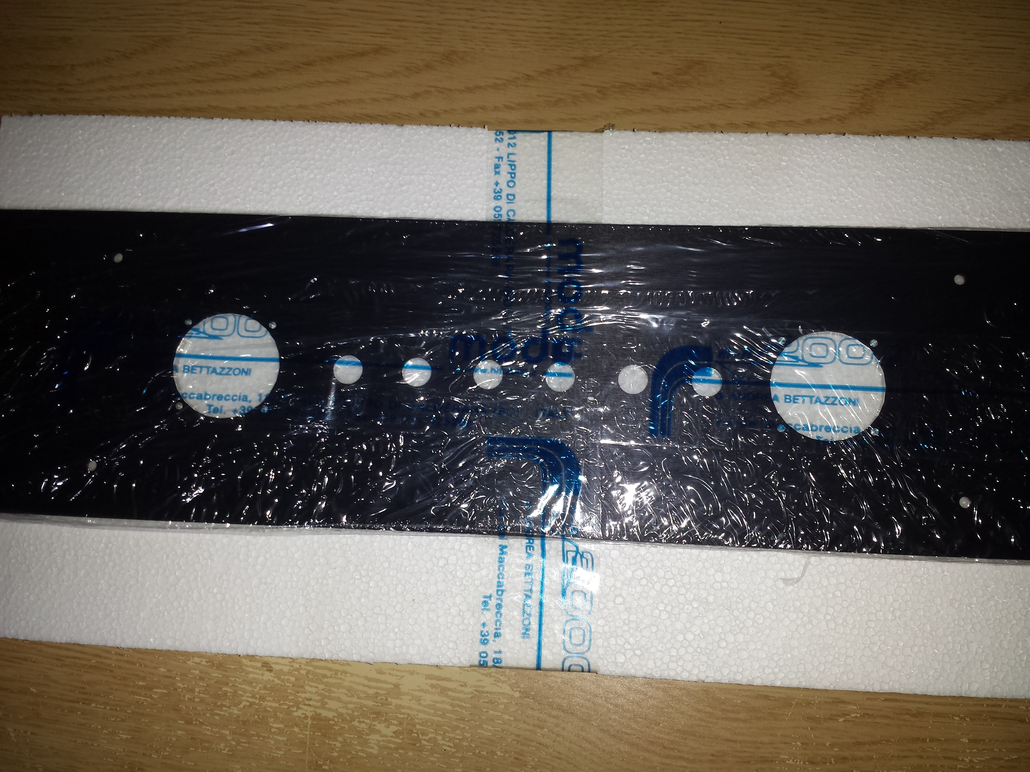
After getting the circuit diagram done I started to thinking about getting an actual box to put it in so I googled around and found a place in Itally (www.modushop.biz) that sold these quite cheap I think it was £50:
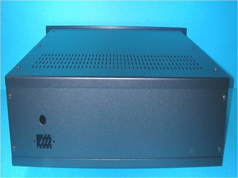
The best part about it was that the company that sells them will modify the enclosure for you for an additional cost, so you will really get a high quality aluminium cnc cut enclosure that will look like anything that costs £1000+ in a Hi-Fi store if you are actually lucky enough for one to have survived in your area.
Before I bought the case I bought all the hardware for it like power sockets, meters and switches in order to measure their dimensions. I then took the cad drawings that I downloaded for free from modushop website and exported them into google sketchup because it's easy to use and then I marked out where everything would go in sketchup adding 1mm to each dimension as a "fit tolerance" to make sure everying had a good chance of fitting together and then I bought the case with all the cad drawings of everything I needed to be cut attached. The total cost was about £120.
Making
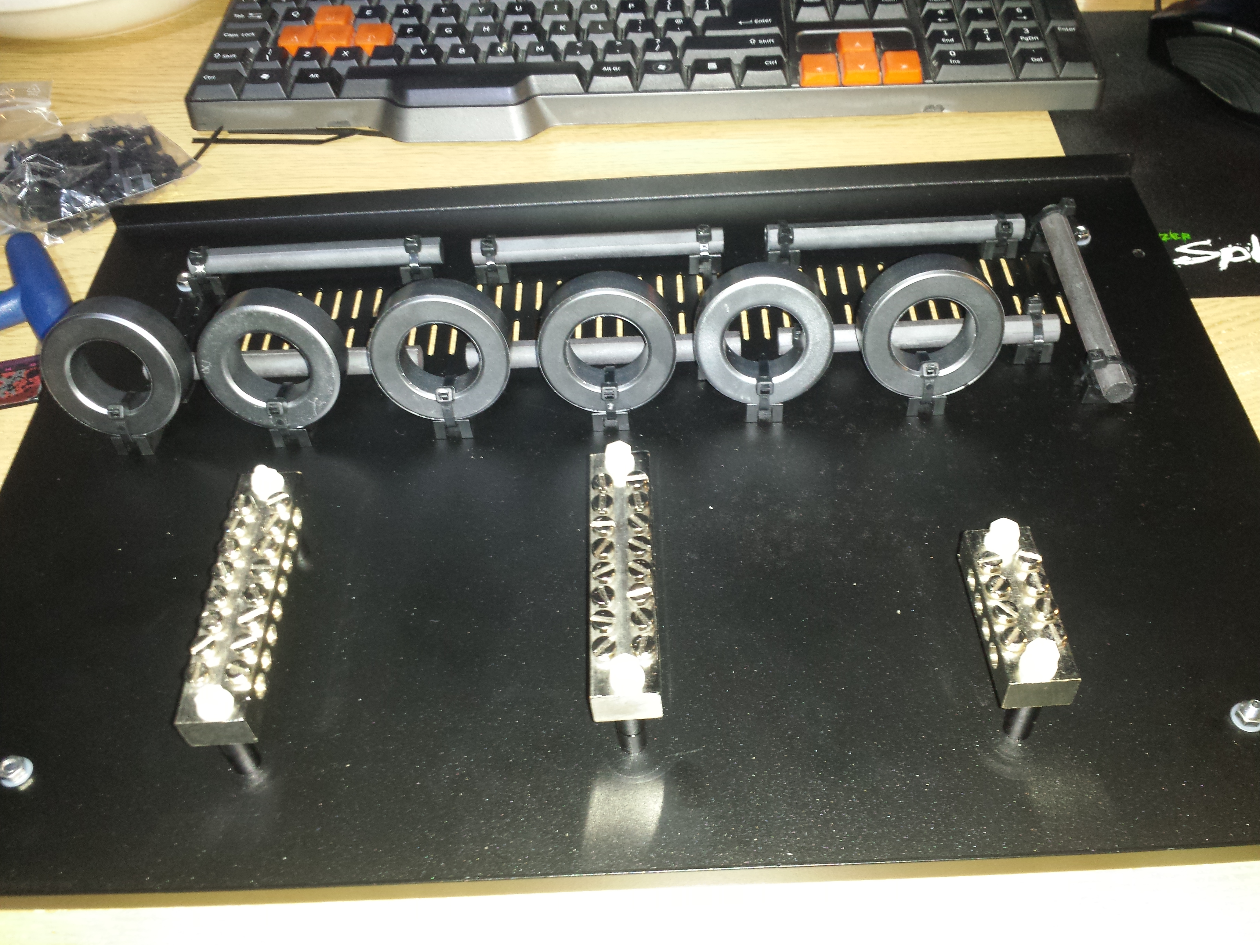
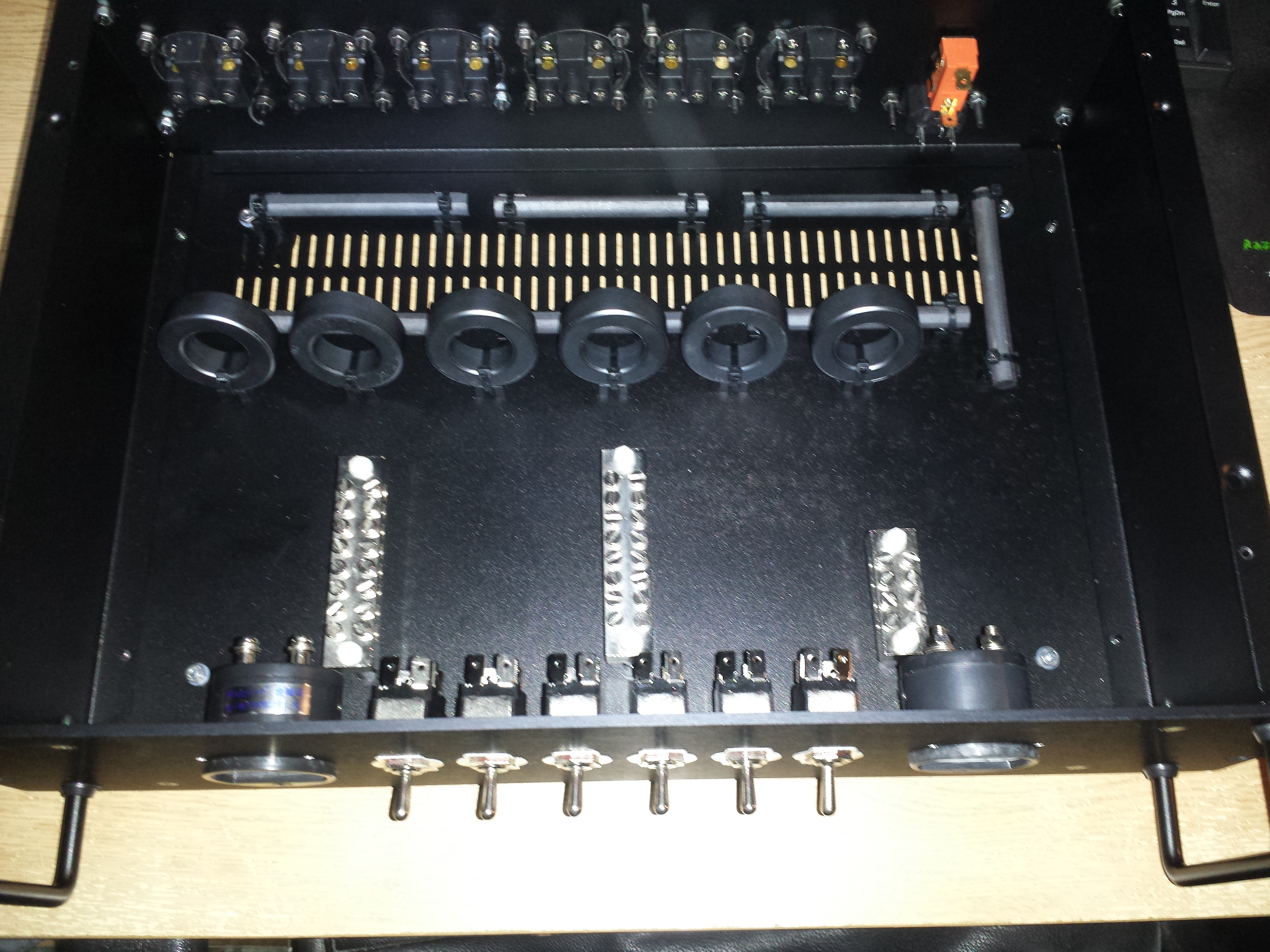
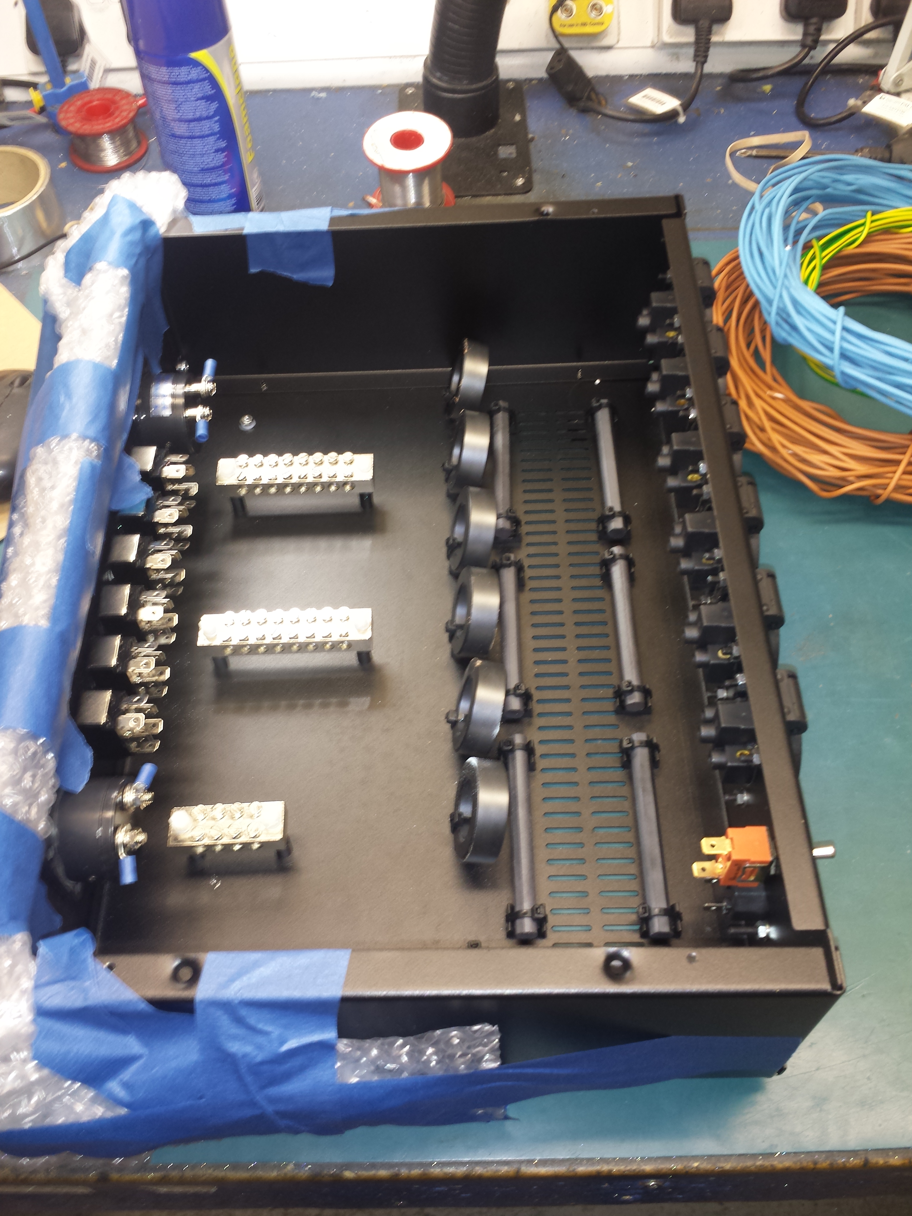
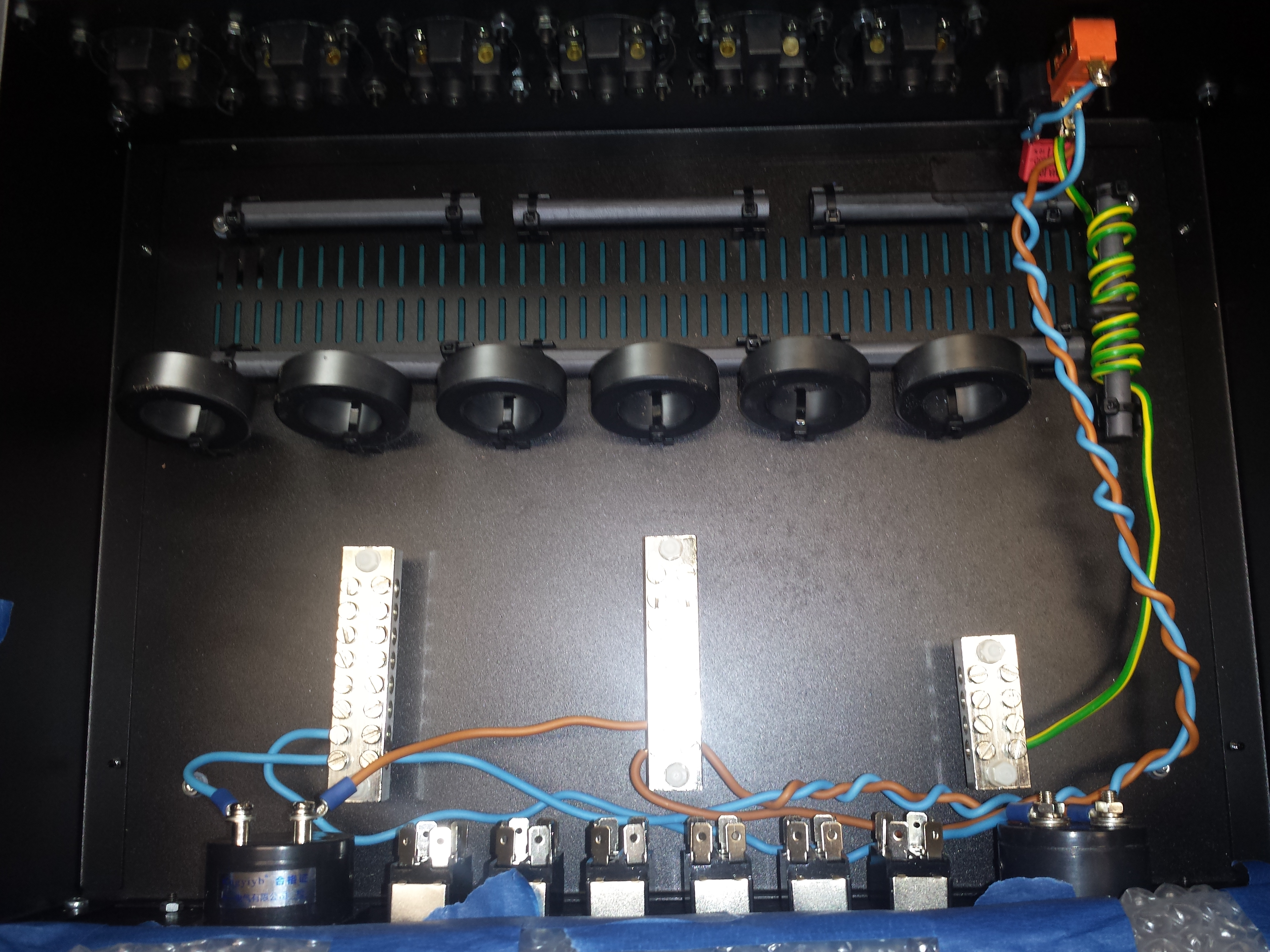
Next, I started to build the circuit insdie the enclosure by drilling all the holes for the 3 commoning blocks, ferrites, sockets, switches and dials. I had to do this by hand because I was building the circuit inside for the first time and didn't know how much space I would require for every single thing including cable routing so I eyeballed it as best as I could and it worked:
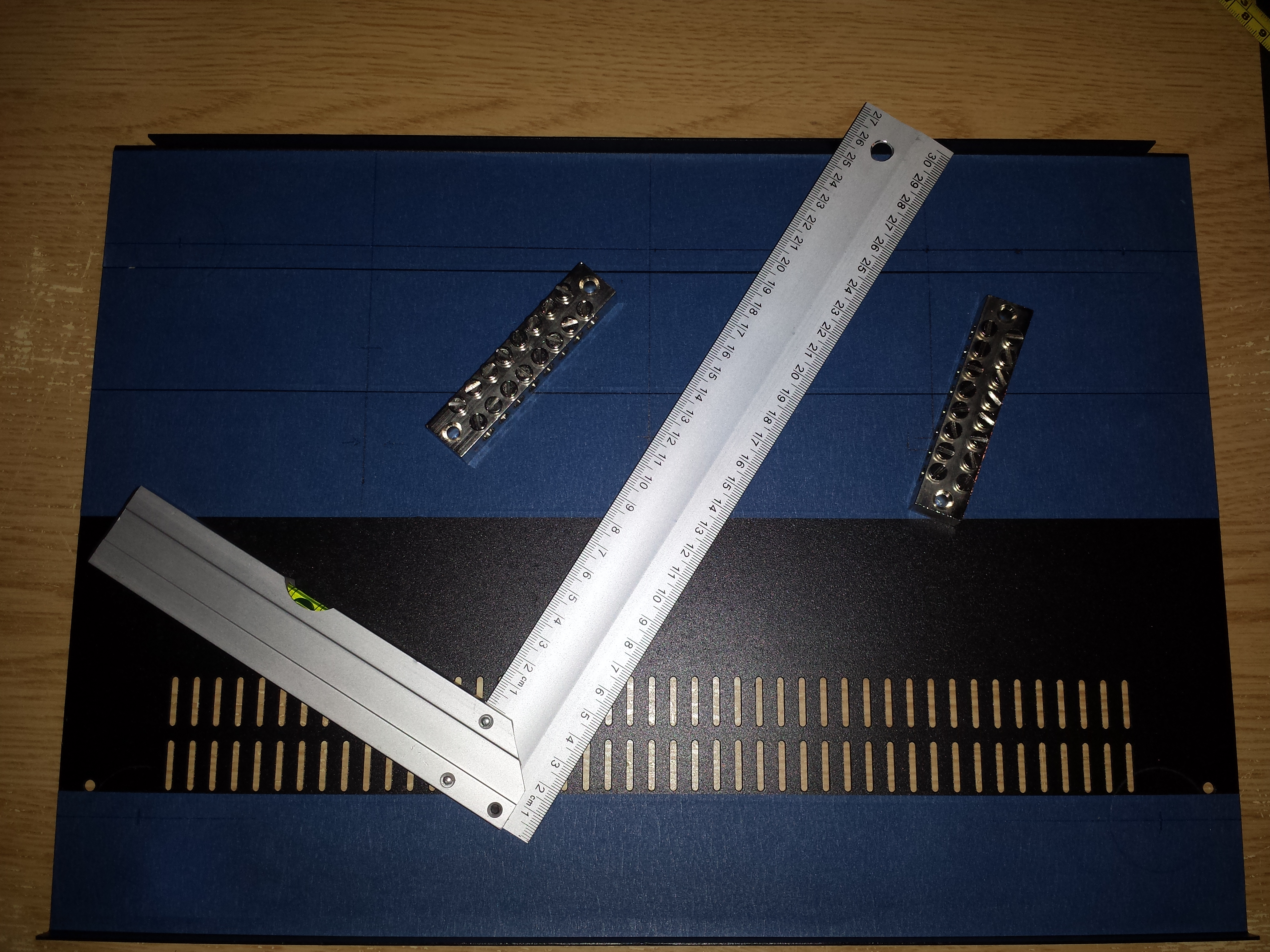
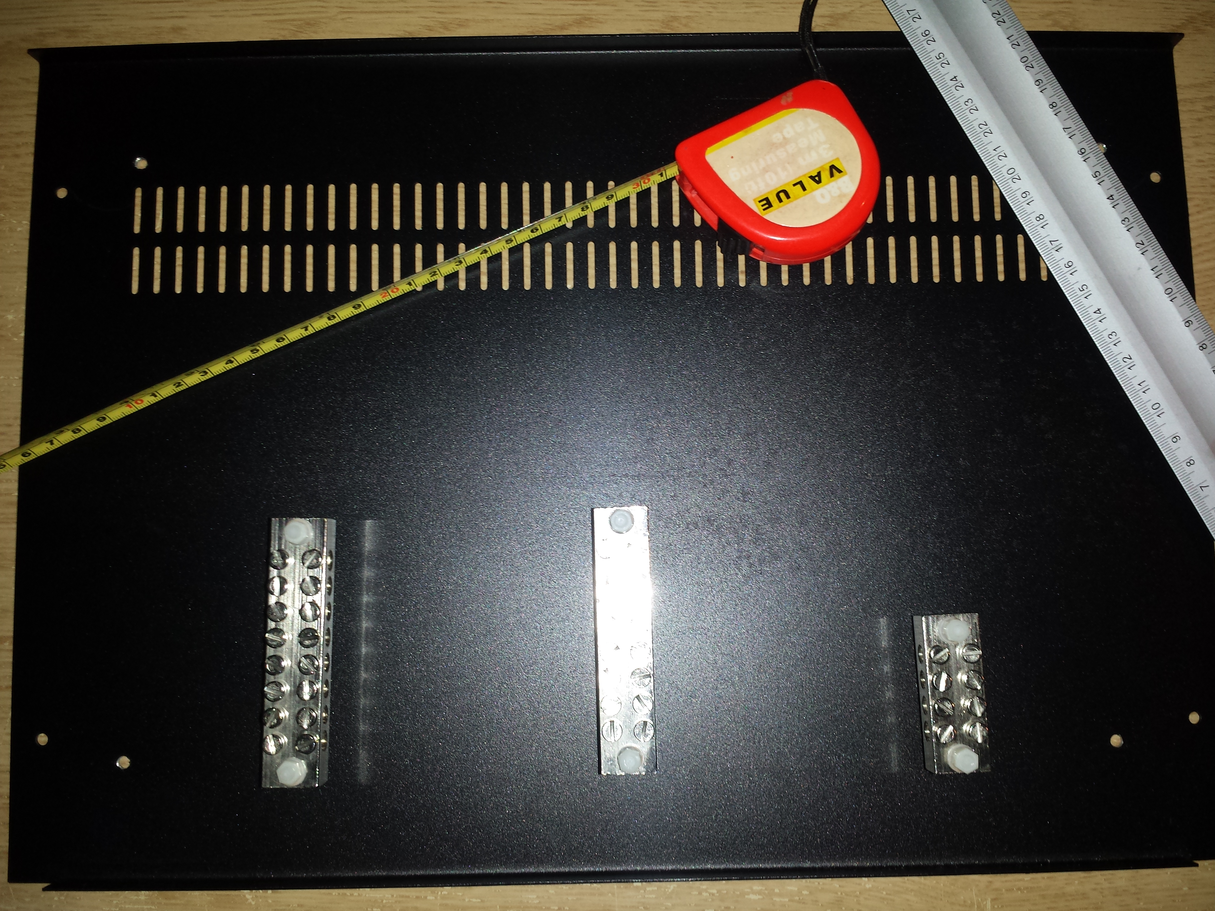
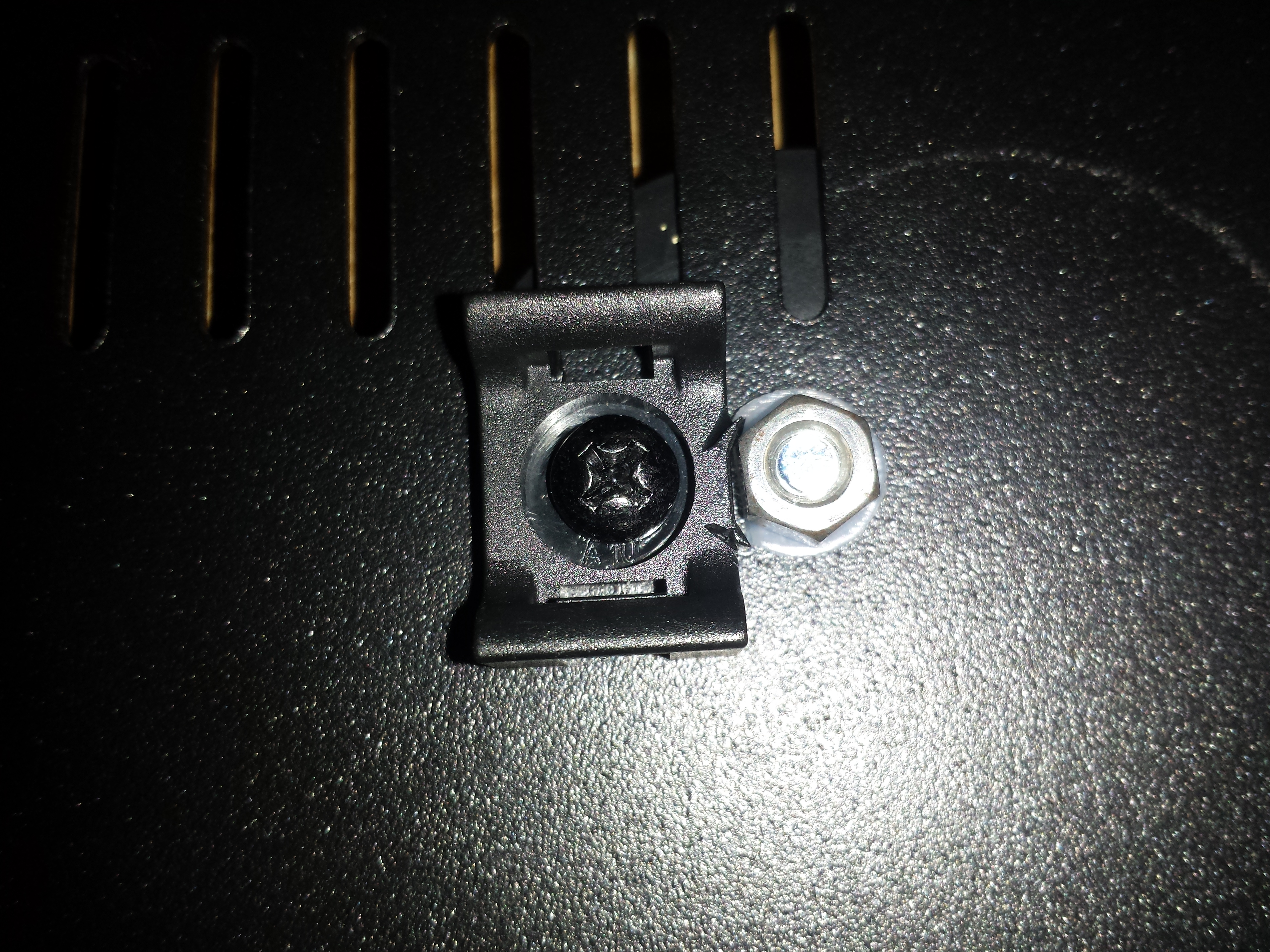
The commoning blocks are lifted off the floor using nylon washers, screws and nuts.
This probably isnt the safest way to do this but If you have a better idea then by all means implement it!
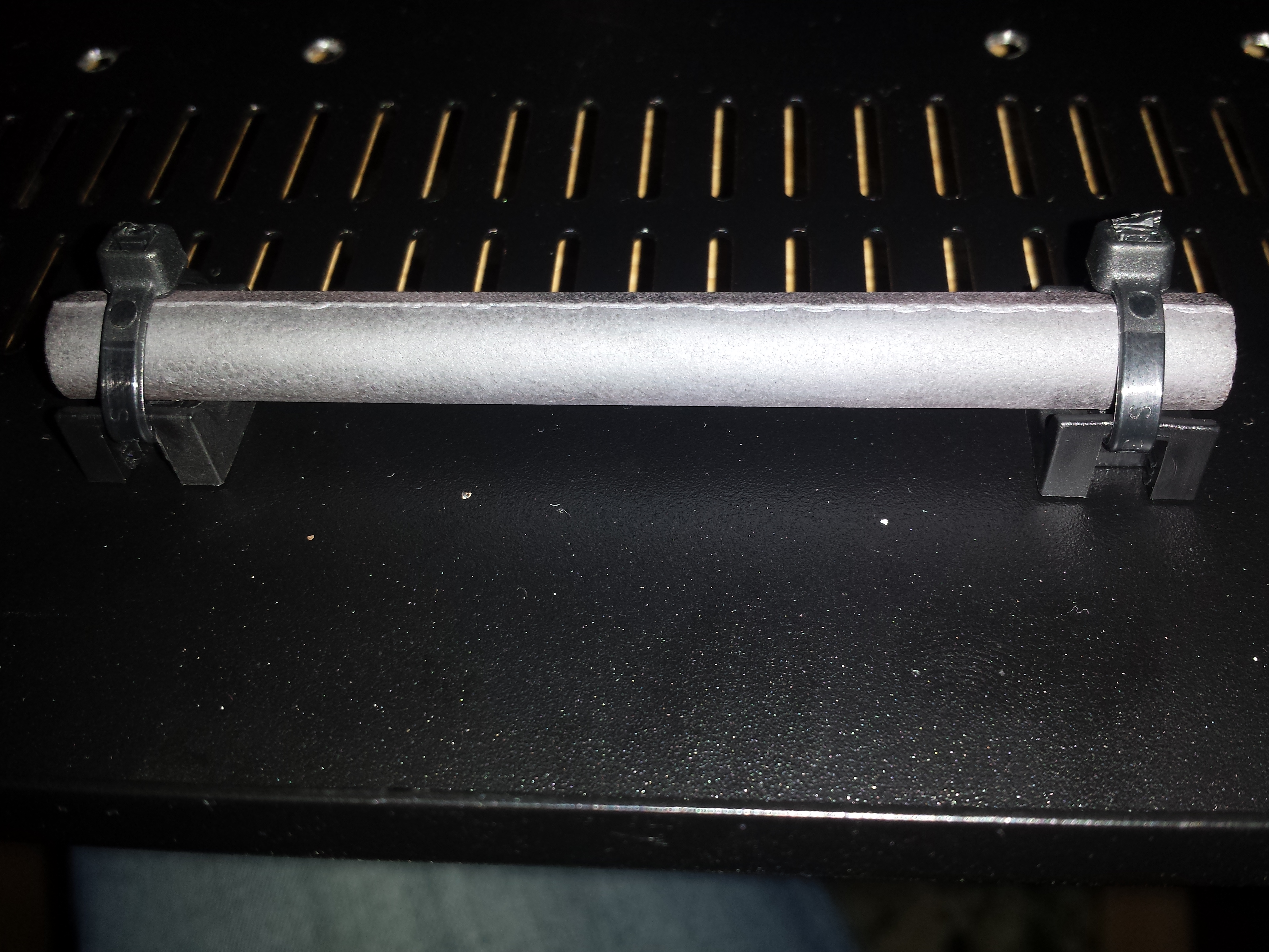
Here is the picture of zip tie anchors used for holdiong down the ferrites:
Example of application
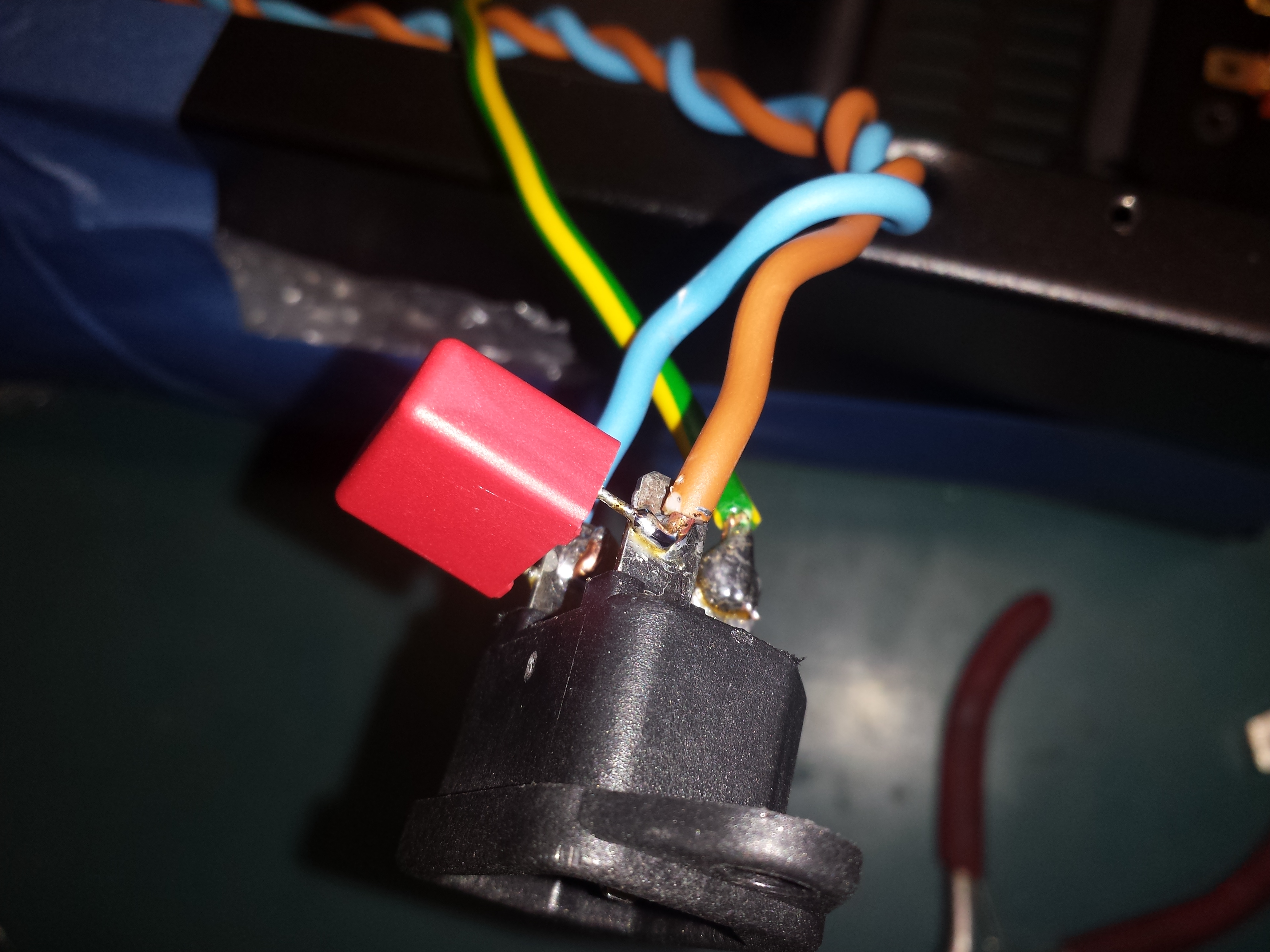
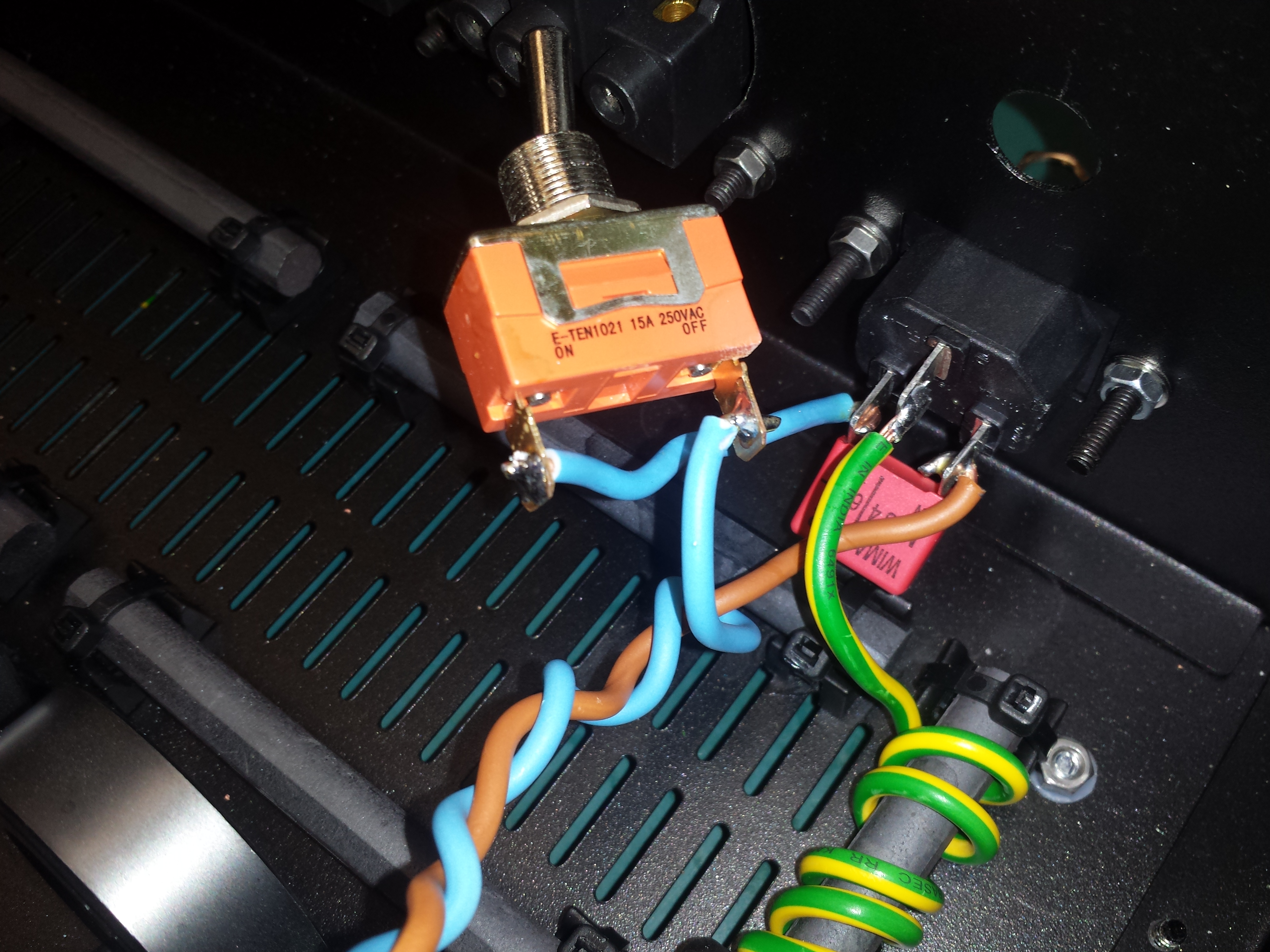
Once all the hardware was inplace on the inside I wired it all up like seen in the circuit diagram above. I started from the start meaning where mains enters the circuit through the IEC conenctor, then to the commoning blocks, then to the switches and then out to the power sockets on the back. REMEMBER the Ammeter dial is to be connected in series and Volt Meter in parallel. I used a solid 2.5mm wire to wire everything up as perscribed by Mr. Lampizator. If you can't find or buy single pieces of 2.5mm wire, get the sort of grey electrical wire you put in the house walls and strip the grey insulation off it and you will get 2 separate 2.5mm cables inside (brown and blue). For the ground wire i used a stranded 2.5mm wire as it justs a ground wire and I didn't see the need for it to be 2.5 and it was impossible to find in the right colour.
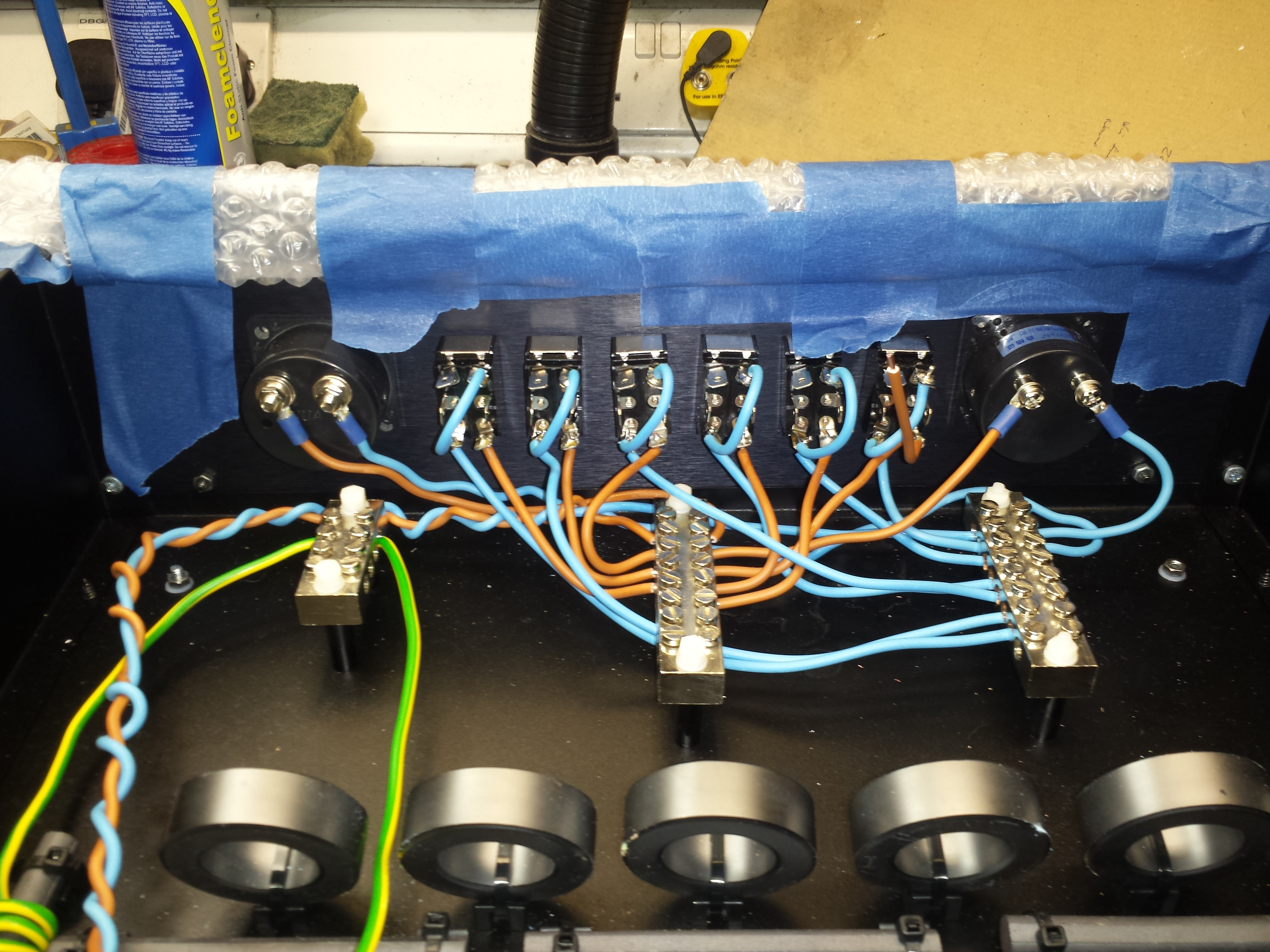
All done:
Obviously I'm not going to show you how to wire everythign up wire by wire because if you can't figure that out yourself using the diagram you probably shouldn't be building this in the first place because you will most likely end up killing yourself.
So thats the circuit side of the project taken care of.
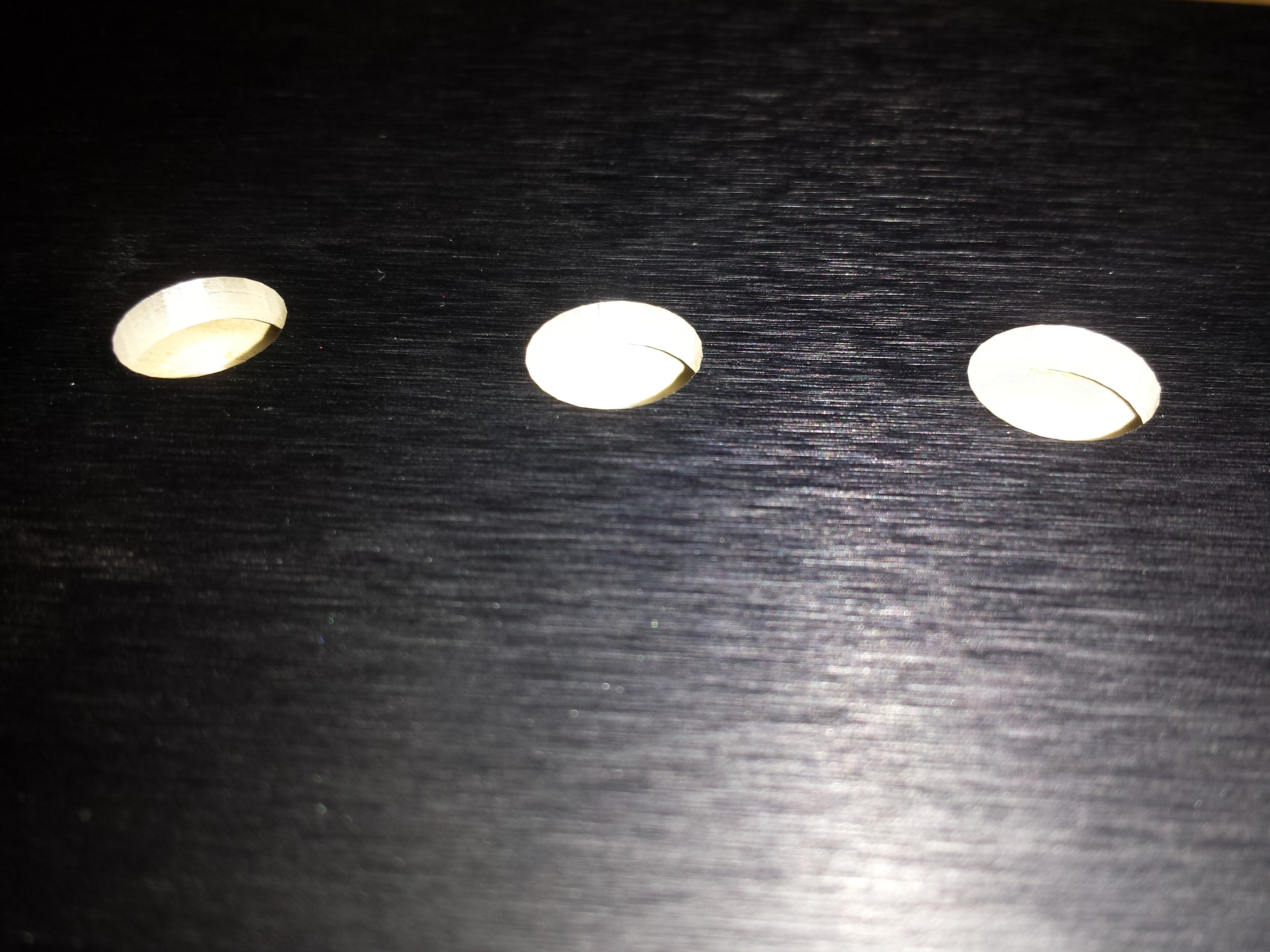
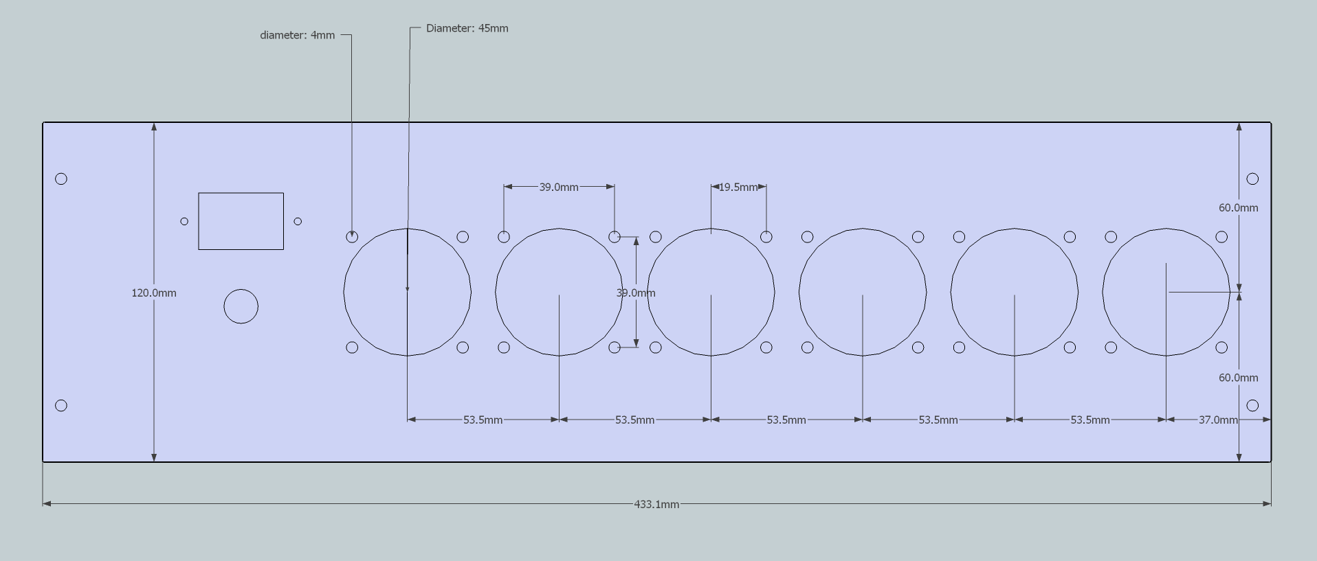
For the fittings, I bought all the fittings and components and measured them with a veriner caliper and then added +1mm to every CNC drawing so that the fit would not be too tight. So for example if a hole was to be 11mm i made it 12mm. This ensured i didnt have to enlarge holes at home with a hand held drill which would destroy the whole "precision look"
I started with the front plate, I measured all the components and made a cad drawing of the front plate as I wanted it. The "blank" drawing of the plate itself was provided for free by the people I ordered the enclosuyre from and ened up with this:
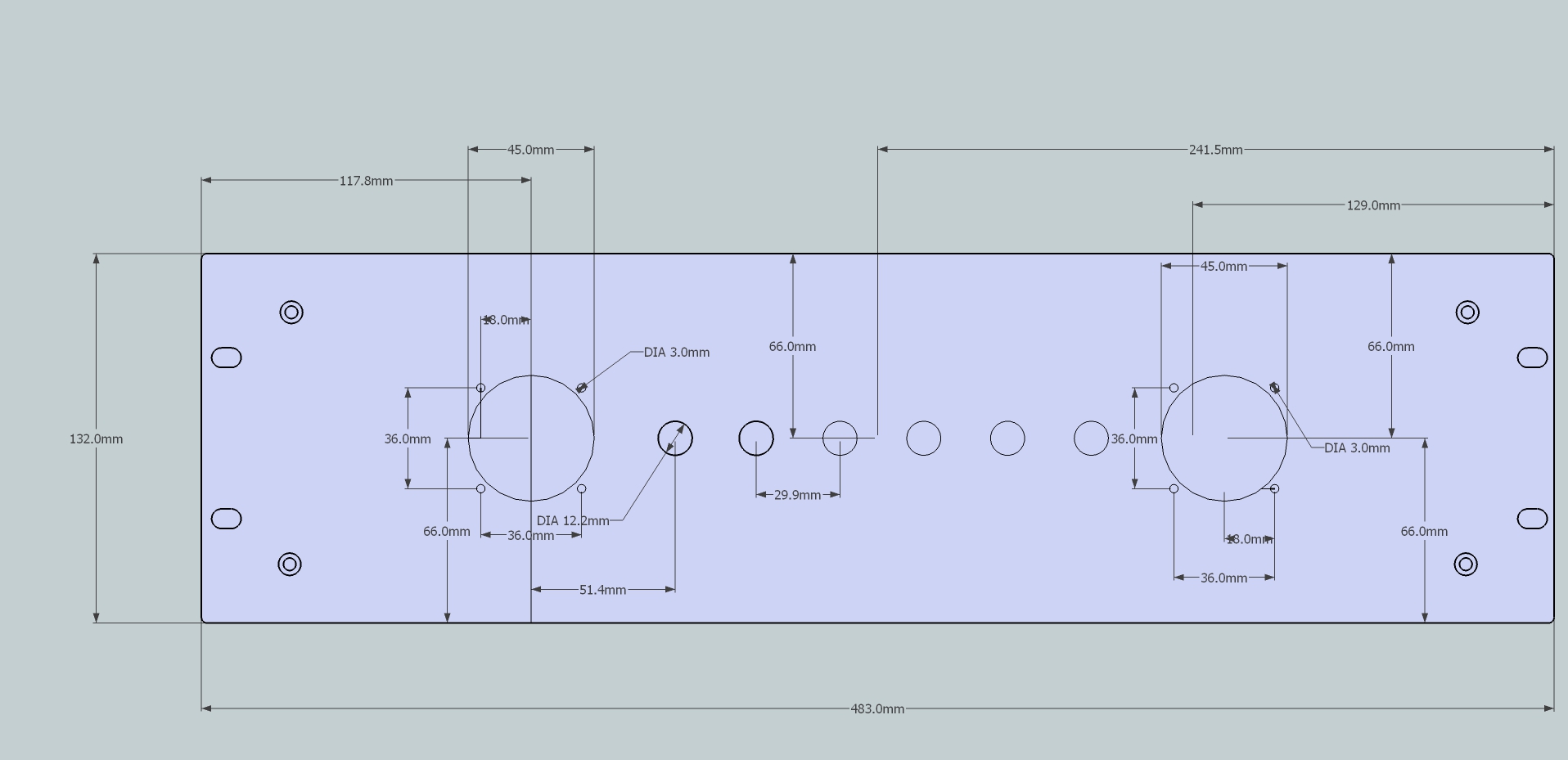
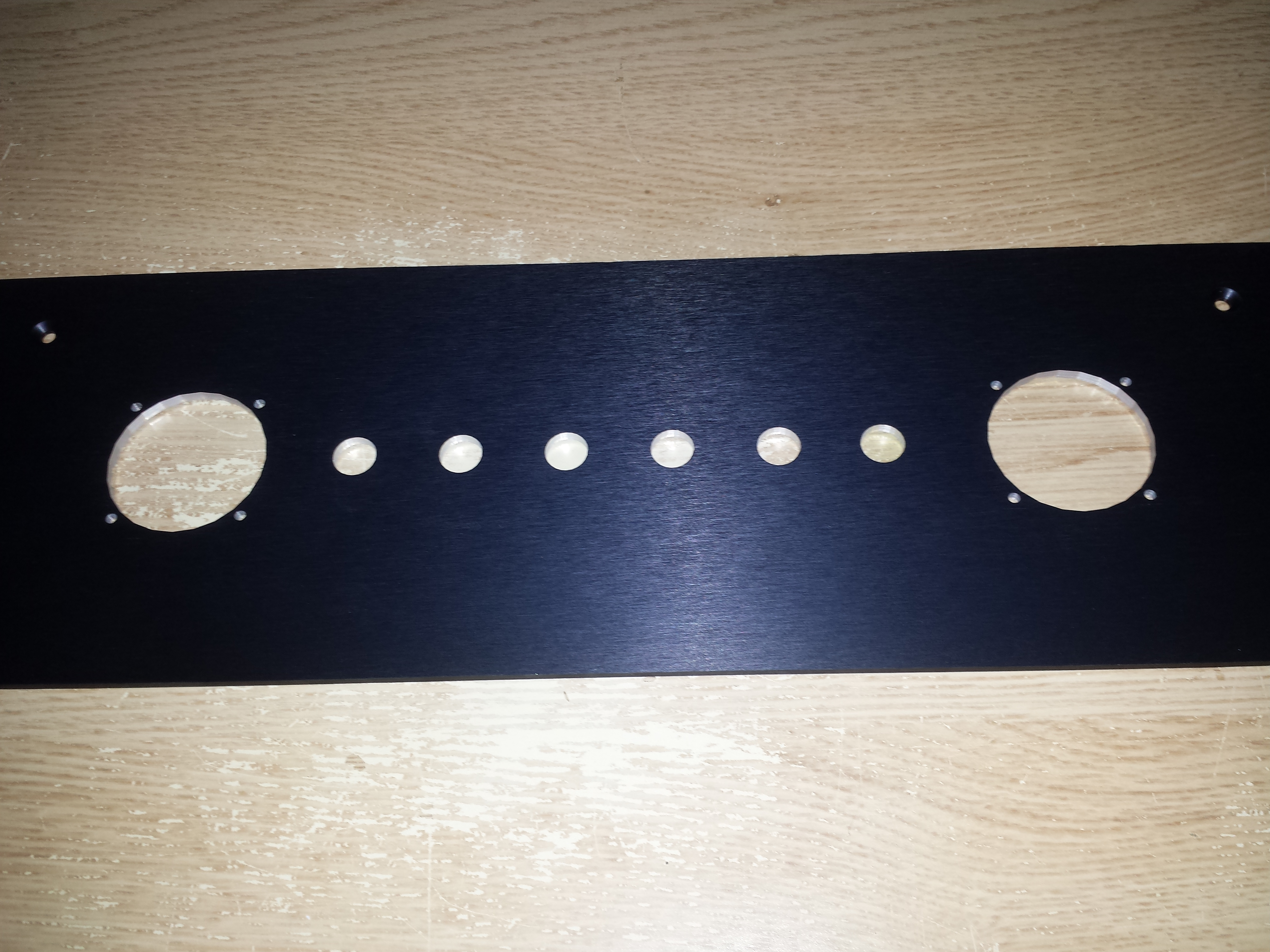
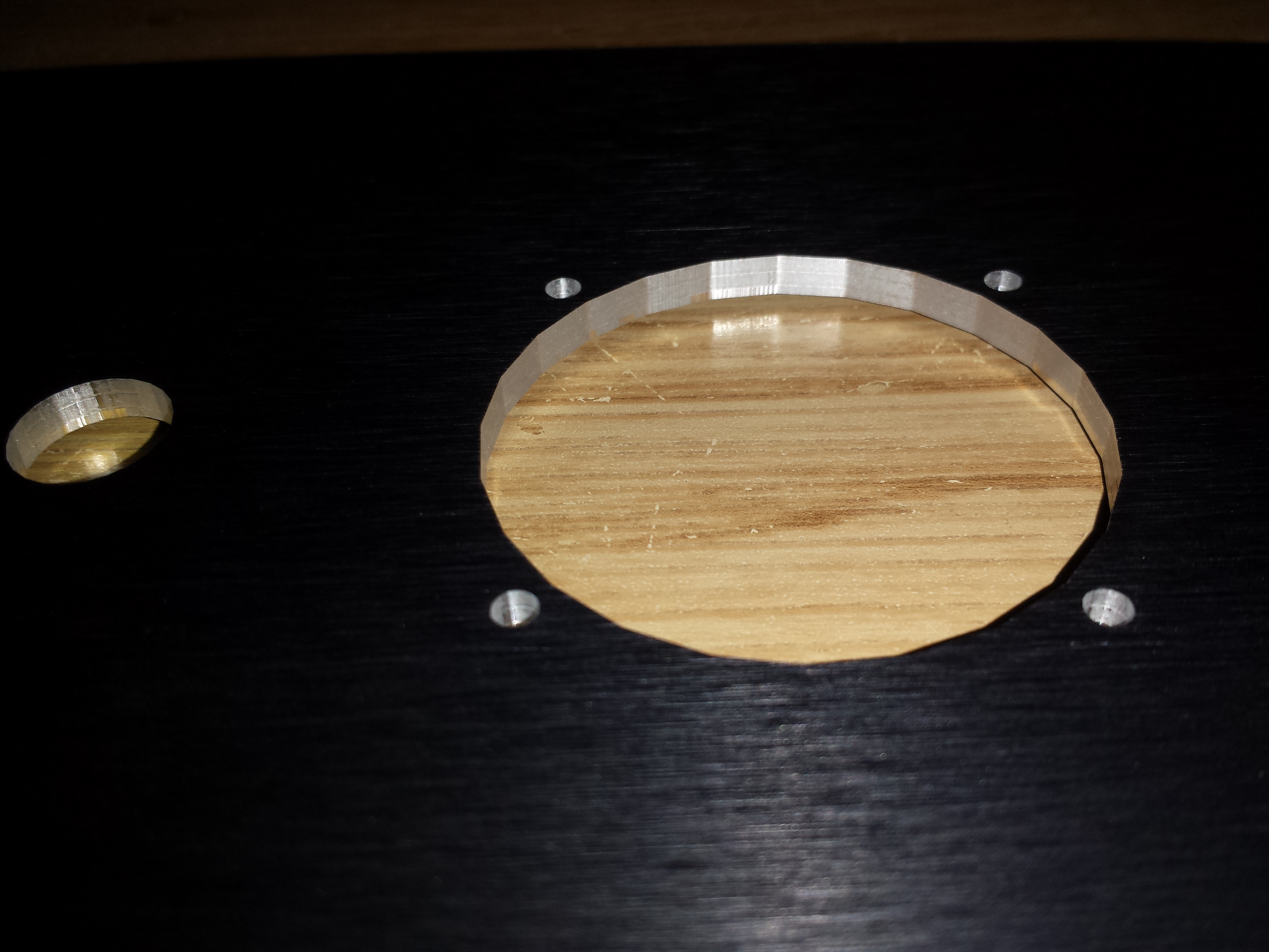
You can see that quality of high speed CNC will alwasys beat you and your hand drill.
Picture of Dials and Switches being installed:
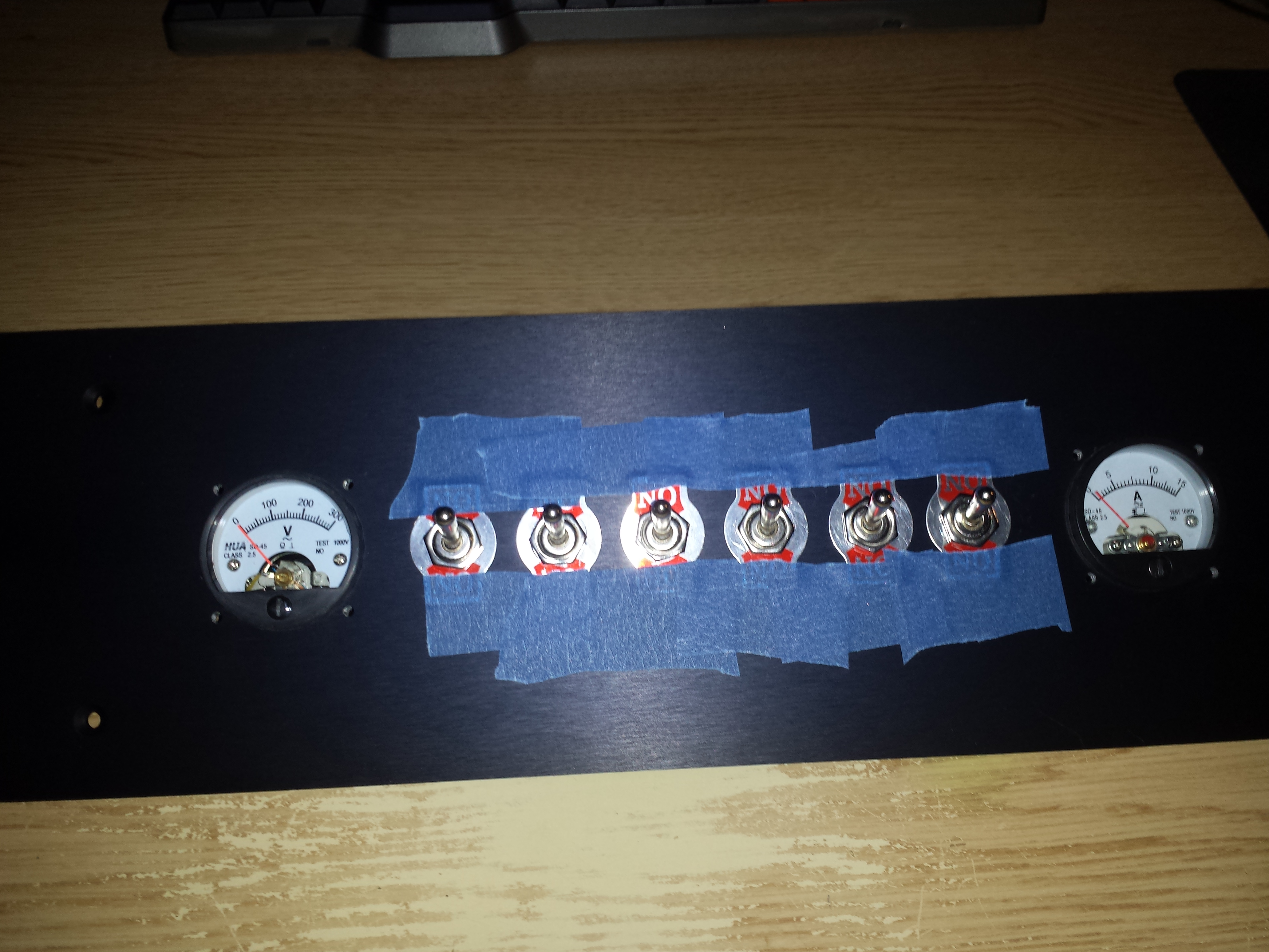
I used tape to hold the face plates of the switches in place as they were wobbly and then I tightened down the nuts.
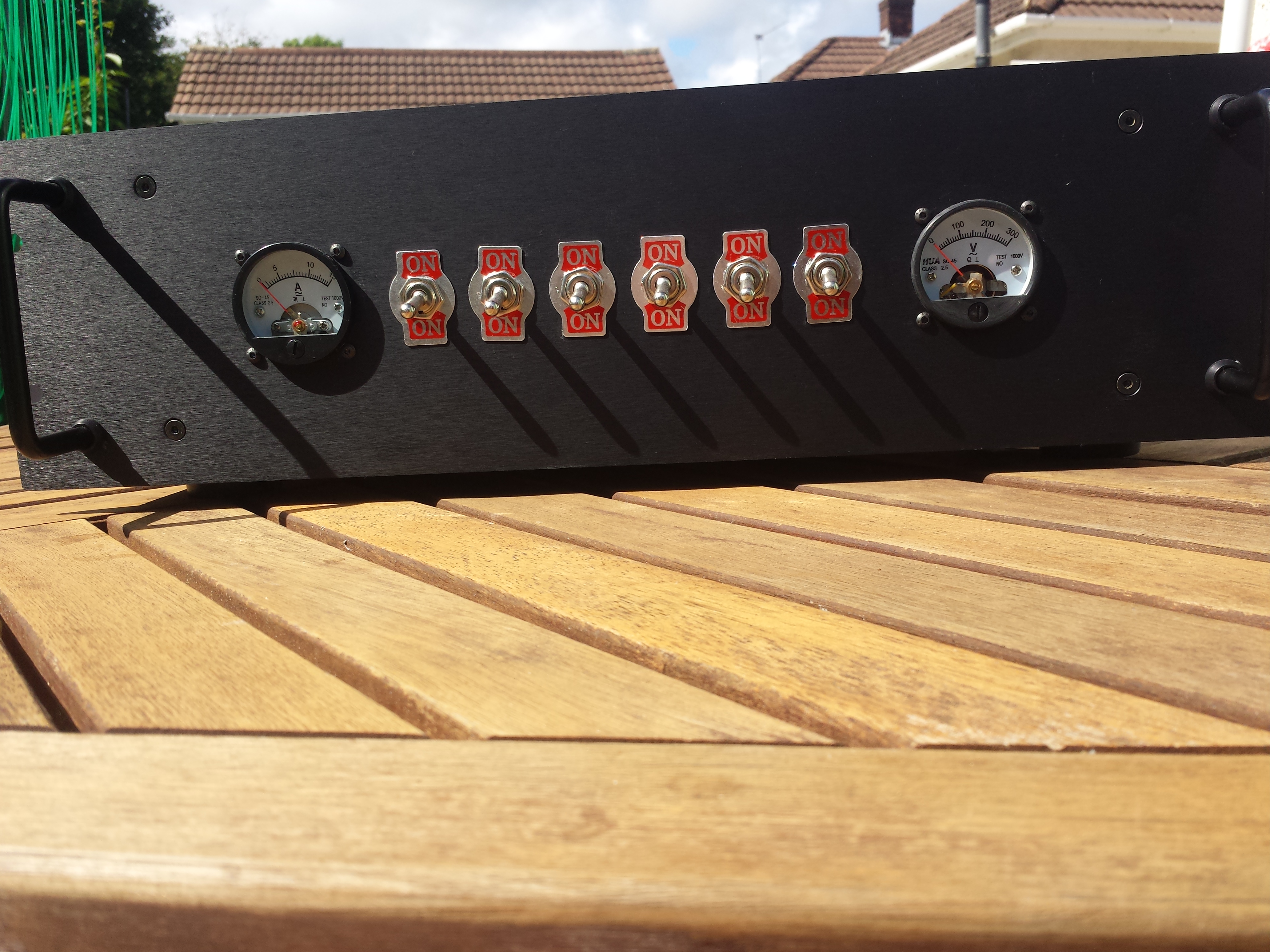
Finished front plate:
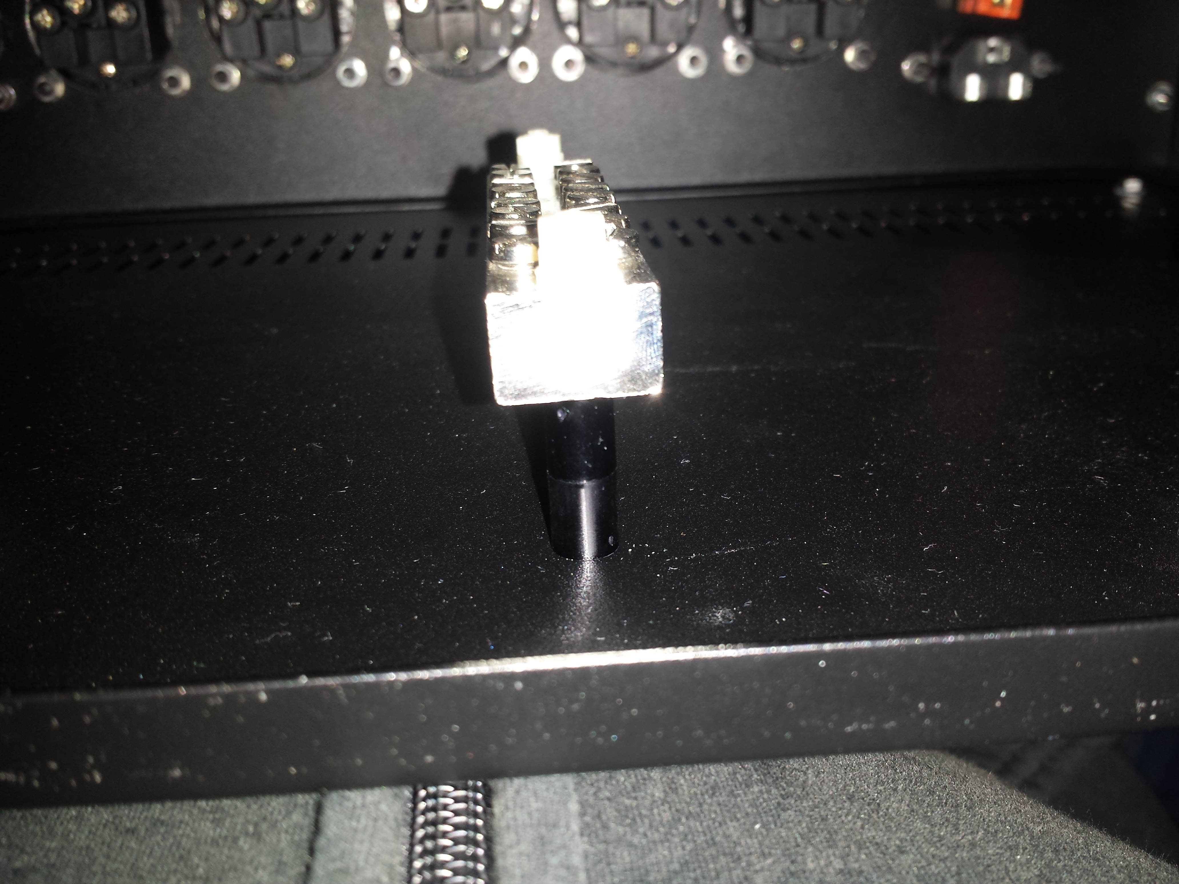
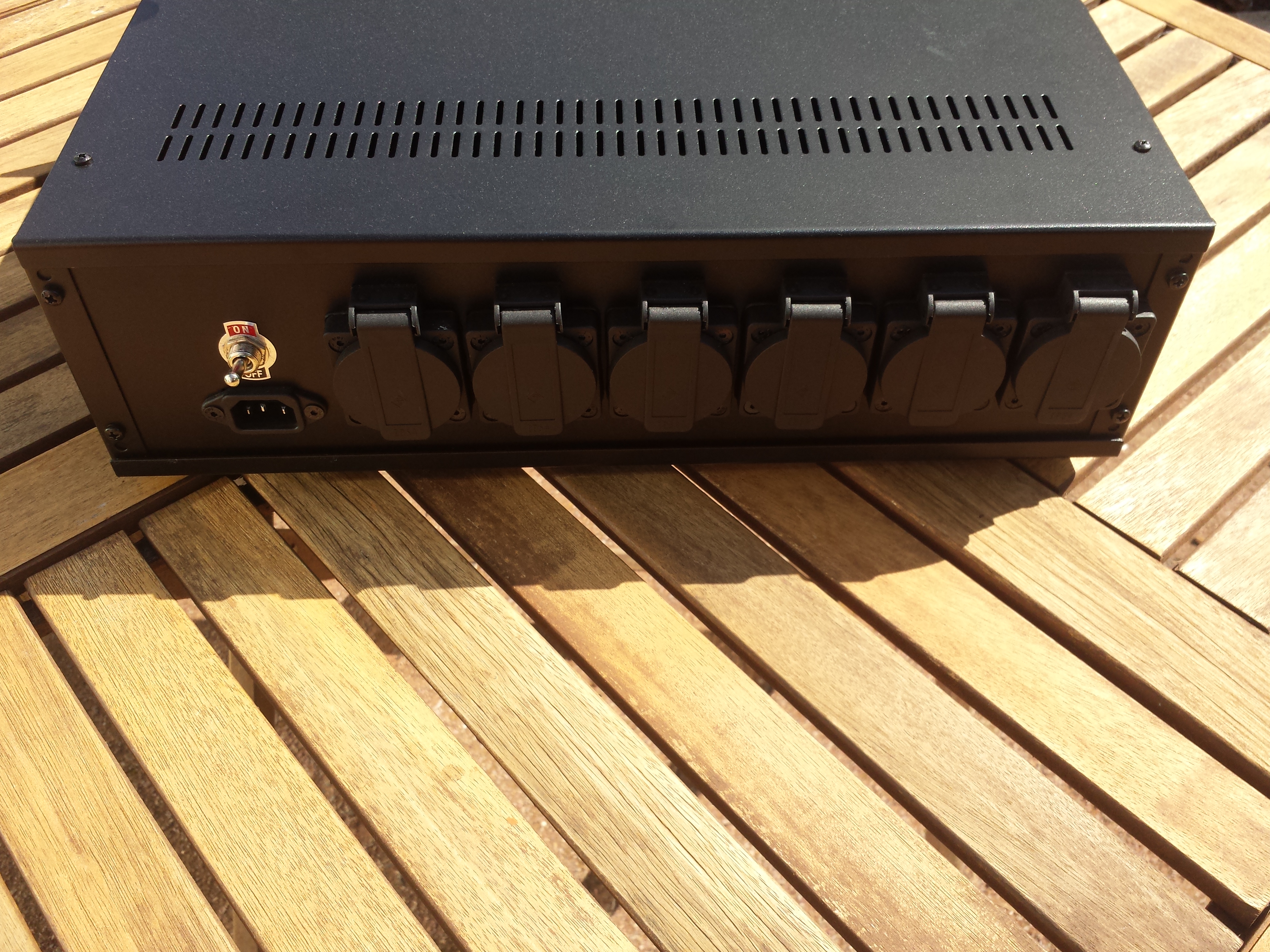
For the back it was a similar story. Just insert the sockets into pefcetly cut and perfectly fitting holes and job done:
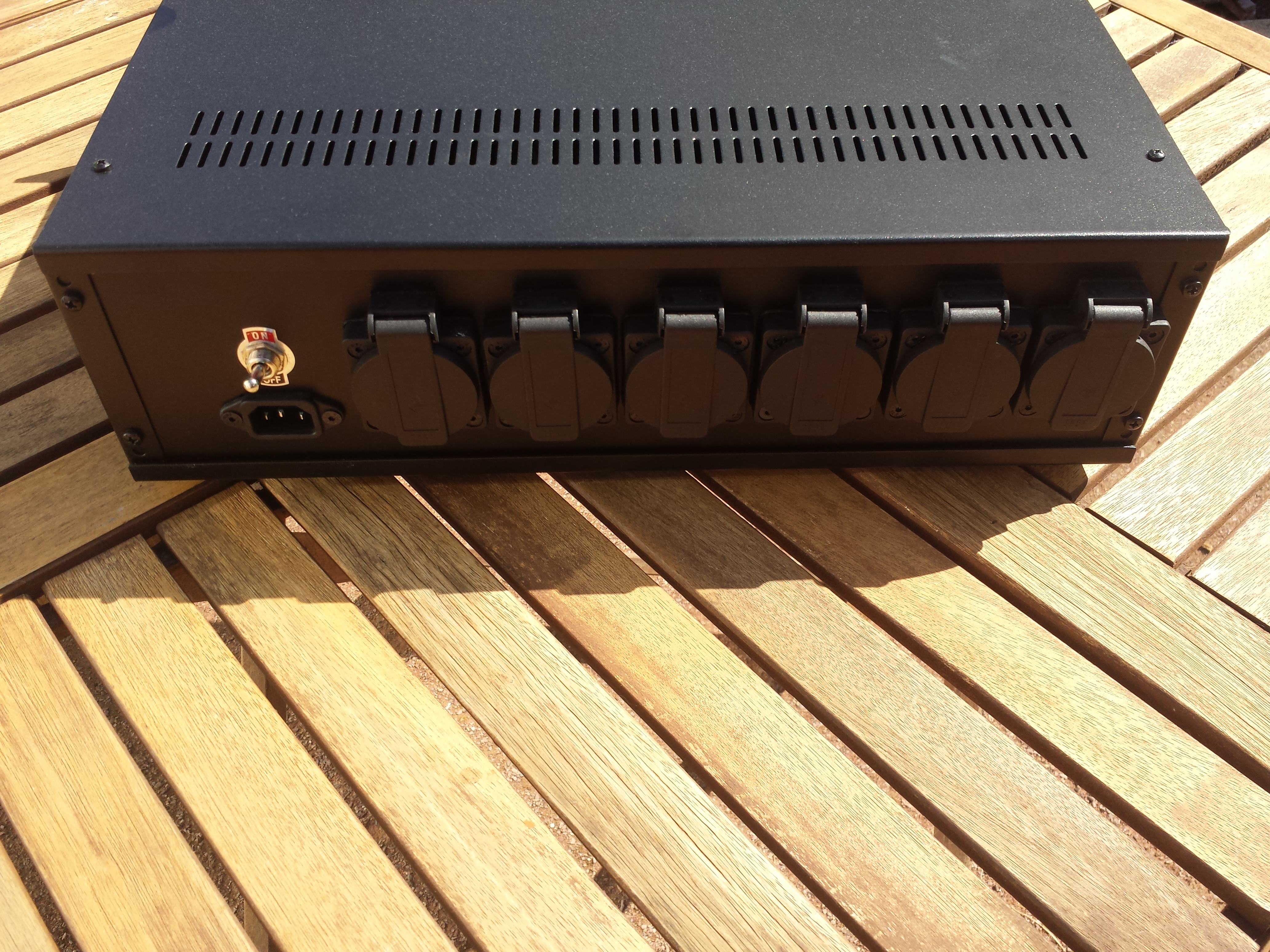
The rear sockets have a flap on them to stop ingress of dust and are black to match the enclosure.
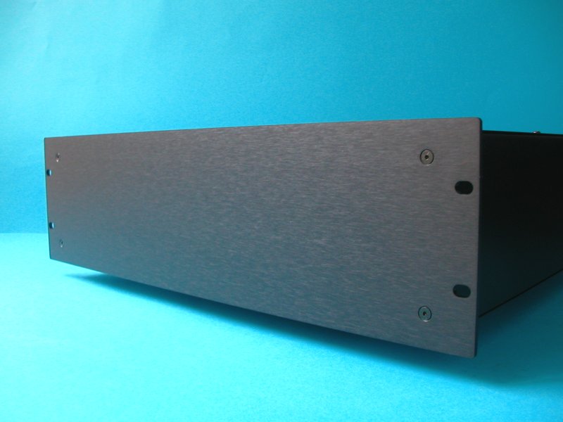
Here are a few pictures of the finished product:
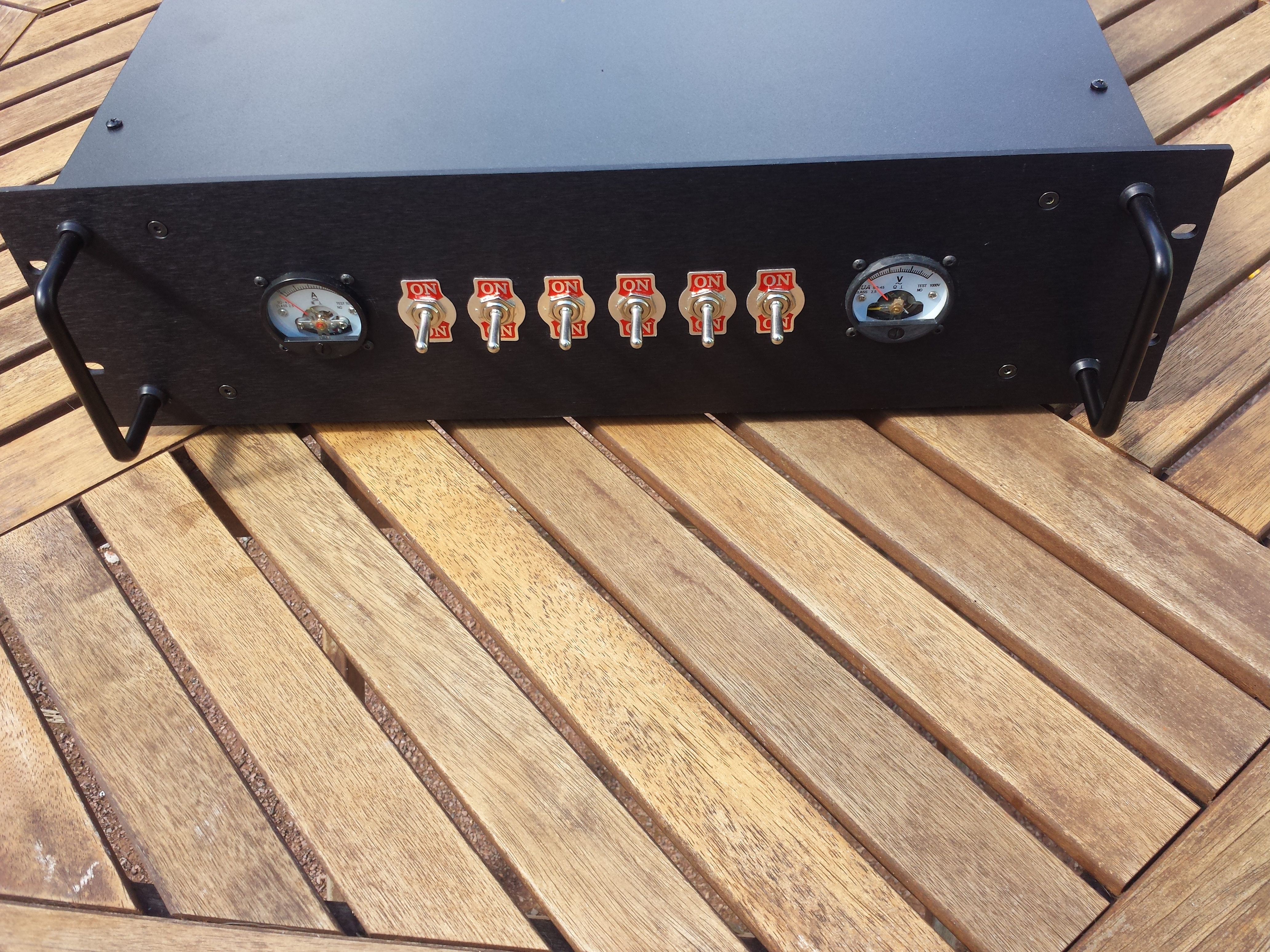
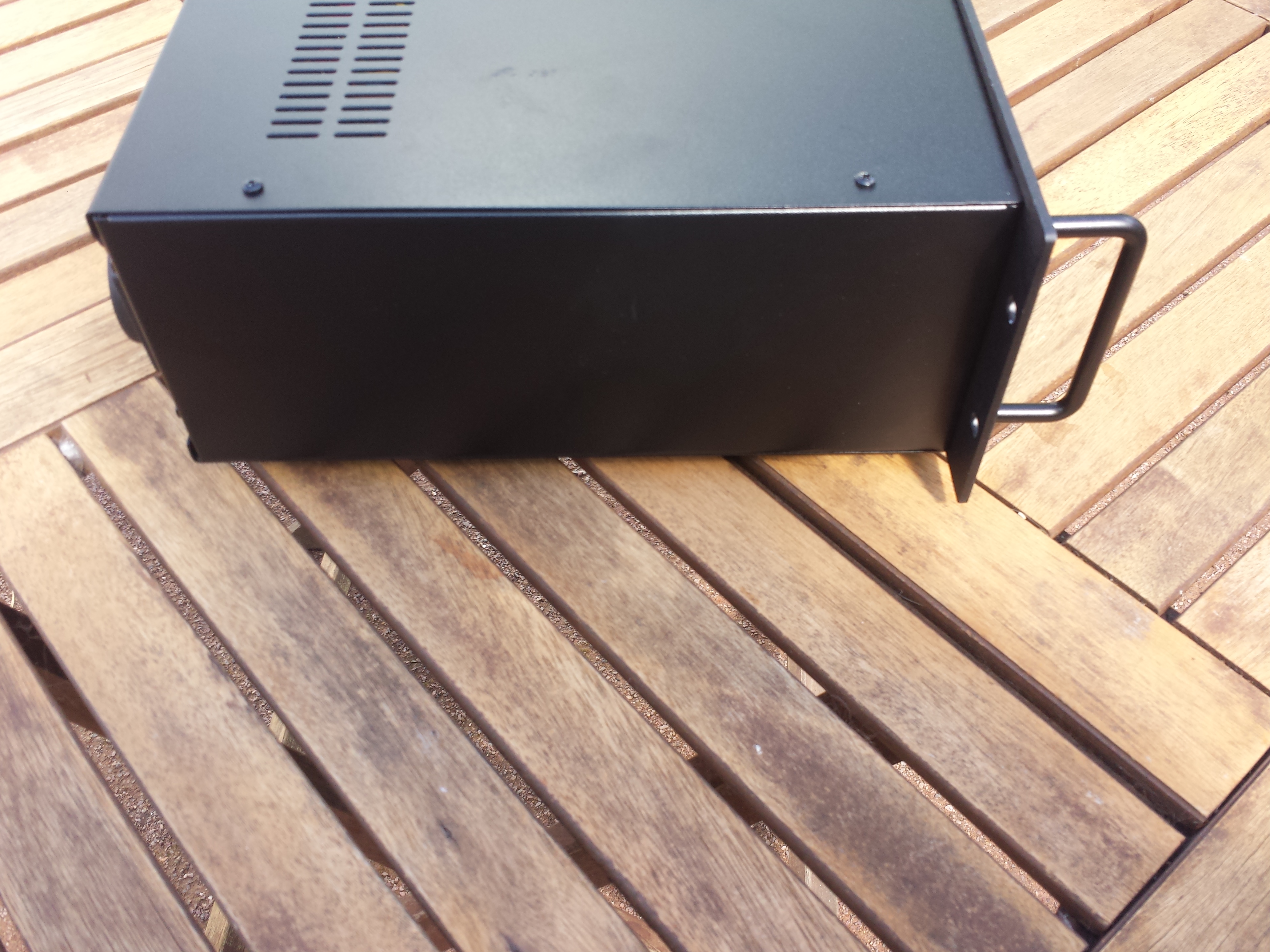
The above "rack handles" were an optional extra and just make the box look cooler
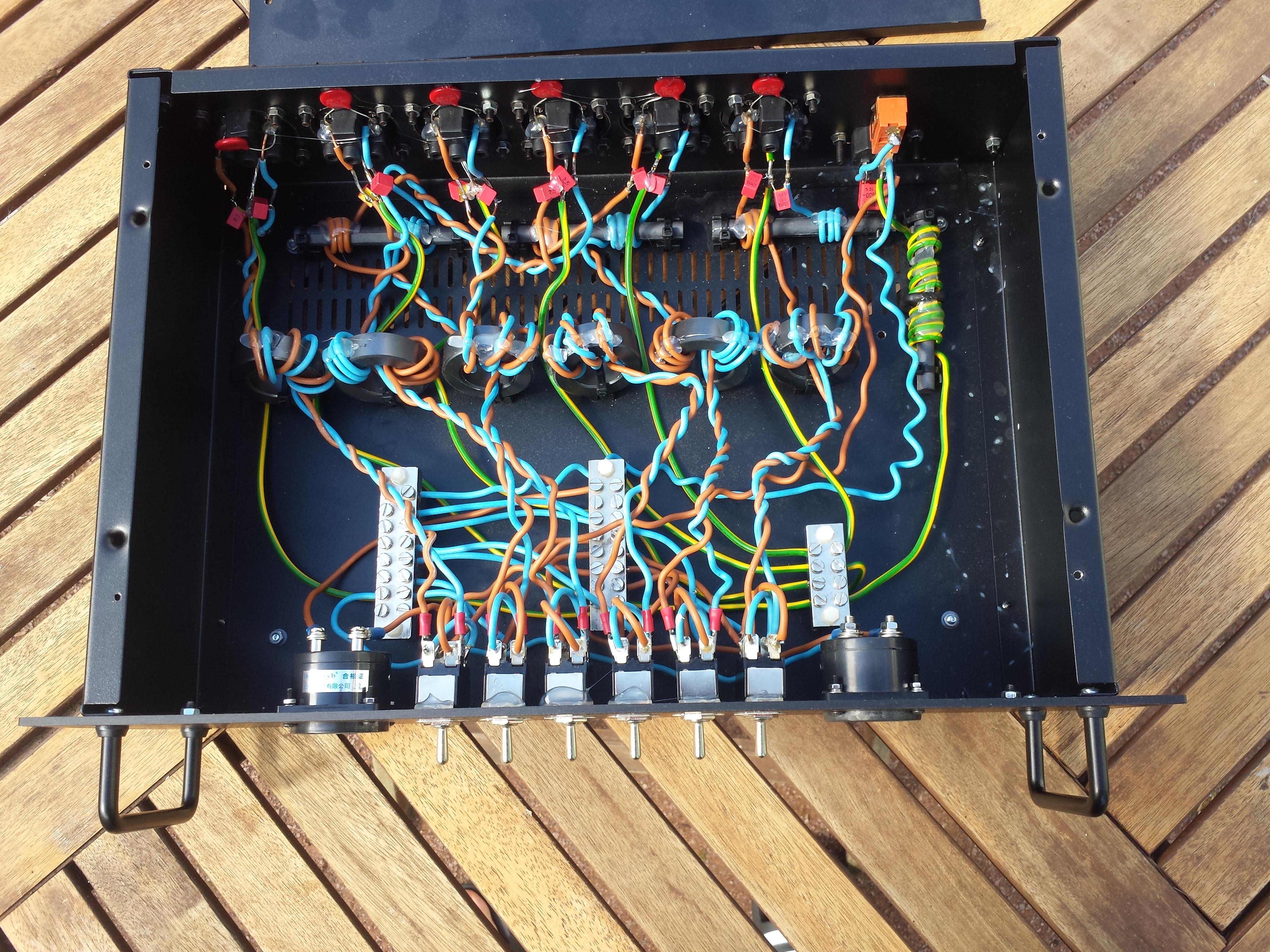
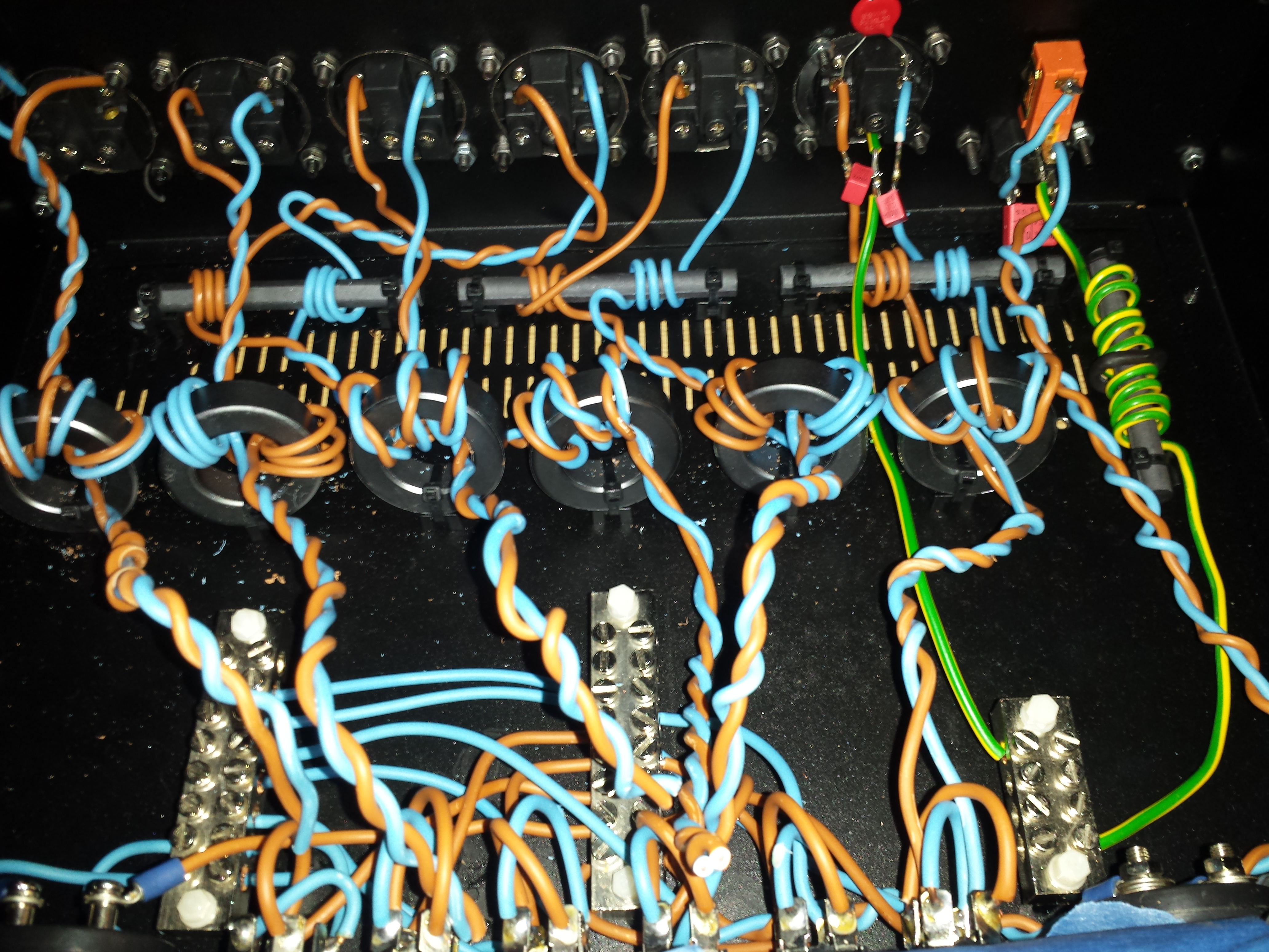
In the end all the cable windings were secured with hot glue to stop them moving about.
To test the circuit for safety and stability I plugged it into the power outlet as usual and connected a bunch of different heavy loads to it such as my pc, electric heater, all my monitors and a laptop for a period of 8h and watched it carefully for any signs of smoke or heat which it completed without any problem.
What's Next
Part 2 of this project will involve testing and seeing if this filter actually makes any audible and quantitative difference. Whatch this space.